
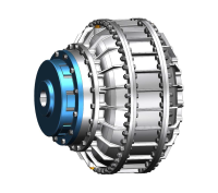
Hydrodynamic Coupling with Double Fluid Units
1. Smoother Start-up with Hydraulic coupling with double fluid units: The dual chambers can be filled with oil in stages or in tandem, achieving an extremely smooth, shock-free start-up, particularly suitable for ultra-high inertia loads.
2. Enhanced Heat Dissipation with Hydraulic coupling with double fluid units: The two chambers provide double the heat dissipation surface area, more effectively dissipating heat generated during operation, suitable for long-term heavy loads or frequent start-stop cycles.
3. Higher Power Transmission with Hydraulic coupling with double fluid units: The dual-chamber design significantly improves torque transmission capacity within similar dimensions.
4. Higher Reliability with Hydraulic coupling with double fluid units: If one chamber fails (e.g., seal failure), the other chamber can still provide partial torque transmission and buffering, resulting in better system redundancy.
- Information
Dual‑Circuit Fluid Coupling
Parallel Hydraulic Paths · N+1 Redundancy · Graceful Degradation
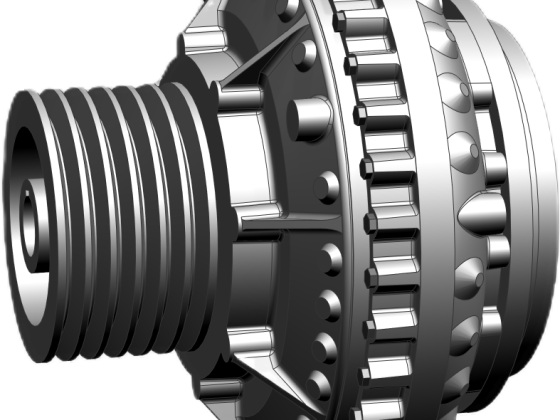
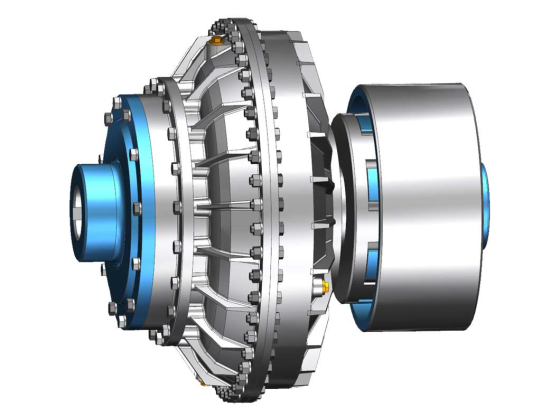
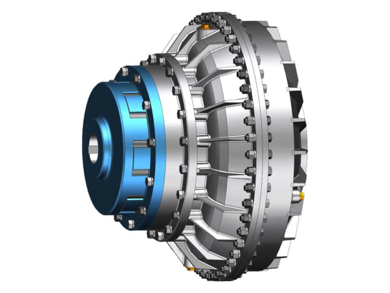
Standard fluid couplings have a single hydraulic circuit: one pump wheel, one turbine, one oil chamber. If that circuit fails – a seal leak, a bearing seizure, or an internal crack – the coupling stops transmitting torque, and the machine grinds to a halt. A Dual‑Circuit Fluid Coupling contains two complete, independent hydraulic circuits inside one housing. Two pump wheels, two turbines, two separate oil supplies, all driving a common output shaft. This arrangement provides true hardware redundancy: if one circuit fails, the other continues to deliver power – at reduced torque, yes, but enough to keep the production line moving until a scheduled repair. For mines, steel mills, and power plants, this “limp‑home” capability is worth millions in avoided downtime.

✔ Core Advantages of a Dual‑Circuit Design
No single point of failure – Each circuit works independently. A leak in circuit A does not drain circuit B.
Parallel torque delivery – Two circuits share the load, reducing stress on internal components and extending bearing life.
Sequential filling option – Fill circuit A first for a gentle break‑away torque, then bring in circuit B for full power – ideal for very high inertia loads like SAG mills.
Double the thermal surface – Two chambers mean twice the wall area for heat dissipation, allowing more starts per hour.
Partial operation after failure – At 50‑60% torque, the machine can still perform essential functions (e.g., rotating a ball mill to change liners, moving a hoist to an unloading position).
? Technical Specifications – Dual‑Circuit
| Brand | Merisen (Dalian Mairuisheng) | |||
|---|---|---|---|---|
| Product Origin | China | |||
| Supply Capacity | 1,500 units/year (scalable) | |||
| Number of Hydraulic Circuits | Two fully independent | Redundancy Type | Parallel “N+1” – one circuit can continue operation after failure of the other | |
| Power per Frame Size | Up to 90% higher than single‑circuit unit of same envelope | |||
| Torque after Single Circuit Loss | Approx. 50‑60% of rated | |||
| Cooling | Dual independent oil circulation + external cooler option | |||
| Certification | ISO9001:2015 | Warranty | 1–2 years (parts and labor, including circuit‑specific repair) | |
| Export Destinations | Russia, Belarus, Kazakhstan, UAE, Romania, and more |
※ Request a failure‑mode effects analysis (FMEA) for your specific drive – we provide it free with quotation.
⚙️ Operational Principle – Independence in Parallel
The input shaft is splined to two separate pump wheels. Each pump wheel accelerates its own hydraulic fluid charge toward its paired turbine. Both turbines are coupled to a single output shaft. The two circuits are hydraulically sealed from each other – there is no cross‑contamination of oil. Under normal conditions, torque splits roughly 50‑50. If one circuit loses oil (seal failure) or suffers a mechanical fault (e.g., turbine bearing seizure), the other circuit continues to operate. The output torque drops, but the shaft still turns. This allows the operator to complete a production batch, move a conveyor to a splice point, or rotate a mill to a repair position. Unlike a single‑circuit coupling where any fault causes an immediate stop, the dual‑circuit design provides a controlled transition to maintenance.
? Critical Applications That Require Dual‑Circuit Redundancy
Main mine hoists (man‑riding or material) – Loss of drive could trap personnel or block ore passes.
SAG and ball mills in remote locations – Even partial torque allows mill rotation for liner or discharge grate inspection.
Long overland conveyors (10km+ ) – A single coupling failure would stop the entire site; dual‑circuit allows reduced‑speed operation to empty the belt.
Ship main propulsion – Redundancy improves safety at sea; one failed circuit still provides maneuvering thrust.
Power plant forced draft fans – Maintaining airflow at reduced capacity prevents boiler trip.
? Customisation for Your Failure‑Tolerance Requirements
? Sequential or simultaneous fill
Sequential for softer starts; simultaneous for quicker response. Configurable via external valving.
? Individual circuit monitoring
Add sight glasses, thermocouples, and oil level sensors per circuit – data to your PLC.
⚙️ Torque bias adjustment
We can set a 60/40 torque split (instead of 50/50) if one circuit is expected to be the “primary” and the other “standby”.
? Spare circuit cassette
We supply pre‑assembled cartridge‑style circuit units for rapid exchange – typical downtime < 4 hours.
Our engineering team (22+ years) will evaluate your risk exposure: cost of an unplanned stop, start frequency, ambient conditions. We then propose a dual‑circuit coupling with appropriate sealing materials (Viton for high heat, FKM for chemicals) and monitoring ports. Every unit is hydrostatically tested per circuit, then torque‑tested on a dual‑dynamometer bench. Worldwide shipping in ISPM15 crates.
? Why Choose Our Dual‑Circuit Coupling Over Two Separate Couplings?
Lower cost – One housing, one set of couplings, one alignment – typically 30% cheaper than two complete fluid couplings installed in series.
Less shaft length – Two separate couplings would require extended motor and gearbox shafts; ours fits in standard coupling space.
Simpler maintenance – Only one guard, one oil system (with two independent circuits), one set of spares.
True “hot standby” – Both circuits are always ready; there is no changeover time.
❓ Frequently Asked Questions – Dual‑Circuit Specifics
? Production lead time for a dual‑circuit coupling?
15‑35 working days – same as single‑circuit because we use common castings and add second internals.
? Can I run indefinitely on one circuit?
No – reduced torque and increased slip generate more heat. You should repair as soon as practical, but the coupling will survive several hours or days depending on load.
? What happens if both circuits fail?
That would require two independent catastrophic failures – extremely unlikely. The coupling would then behave like a failed single‑circuit coupling (zero torque).
? Do you offer a 3‑circuit design?
Yes, for extreme criticality (nuclear, chemical). Contact us for multi‑circuit custom engineering.
? Export packaging?
ISPM15 certified fumigation‑free wooden crates, sea‑worthy.
? Payment terms?
30% T/T advance, 70% against BL copy. LC also accepted.
? See the Dual‑Circuit Cutaway
Animation showing two independent circuits, how torque splits, and behaviour after one circuit oil loss.
? Request a Redundancy Analysis and Quotation
Tell us: motor power, driven machine (hoist, conveyor, mill), start frequency, and acceptable downtime. We'll return a FMEA table and a dual‑circuit coupling proposal within 24 hours.
? WhatsApp: +44 7564 215872
✉️ Email: info@mrscouplings.com
? Dalian Mairuisheng Transmission Mechanism Equipment Co., Ltd.
? Ganjingzi District, Dalian City, Liaoning Province, China
We respond within 24 hours with dedicated engineer support.
Dalian Mairuisheng – Dual‑Circuit Fluid Couplings | Founded 2004 | ISO9001 | Redundancy Engineered for Unplanned‑Stop Criticality